Goal
Building a electronic entry system to our hacker space which is able to lock and unlock the front door in a secure manner. To simplify and make it easier to reproduce, I will use a KeyOmatic and modify it for our needs.
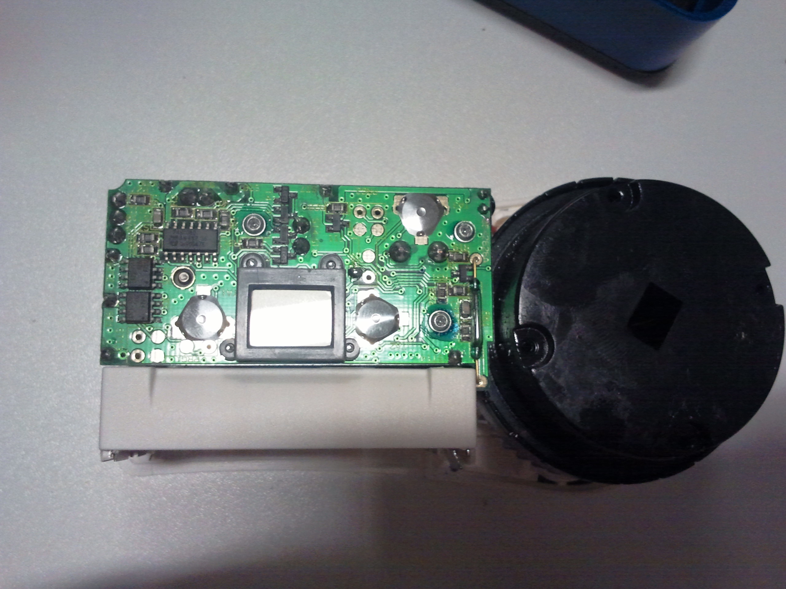
Hardware inside the KeyOmatic
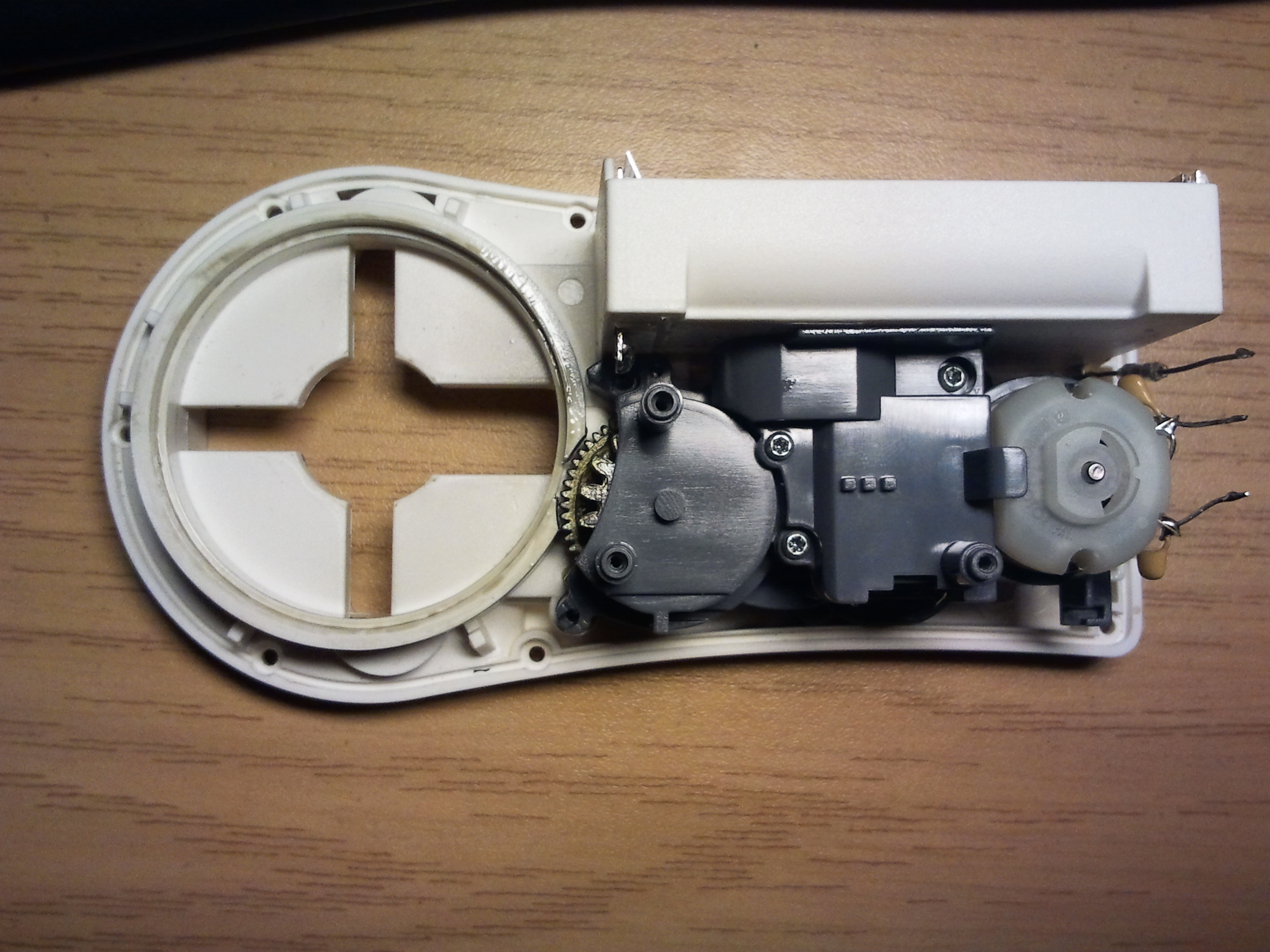
- battery container: space for three AA-Batteries
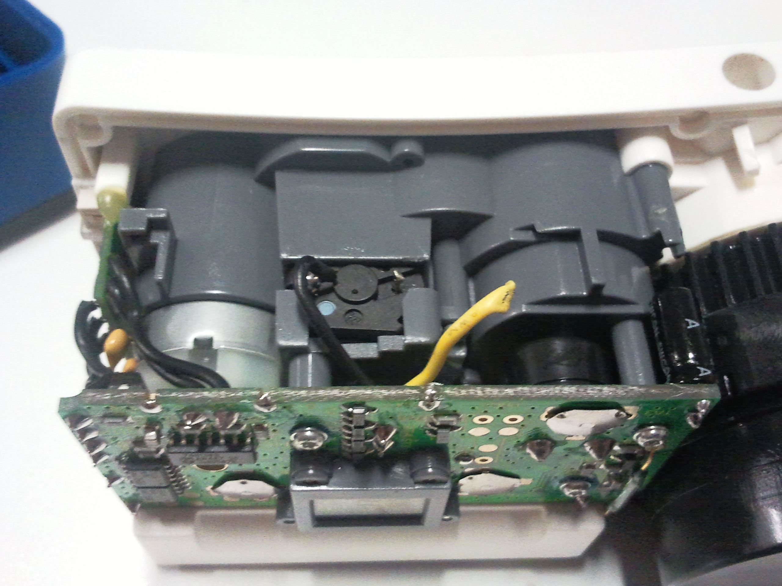
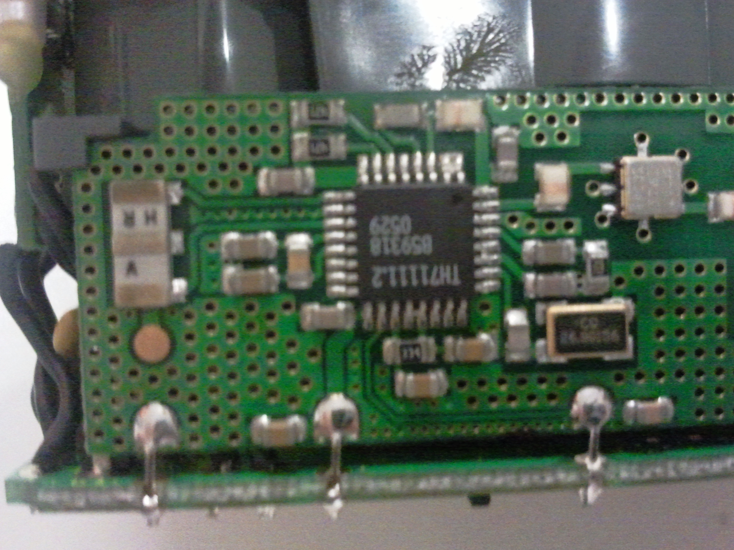
- wireless board: board with the wireless chip and antenna. Can be removed without removing any other function of the device. It is only connected by 3 solder points.
- bus board: connected to the main board by 5 solder points it contains only a few resistors etc and bus connectors for additional hardware
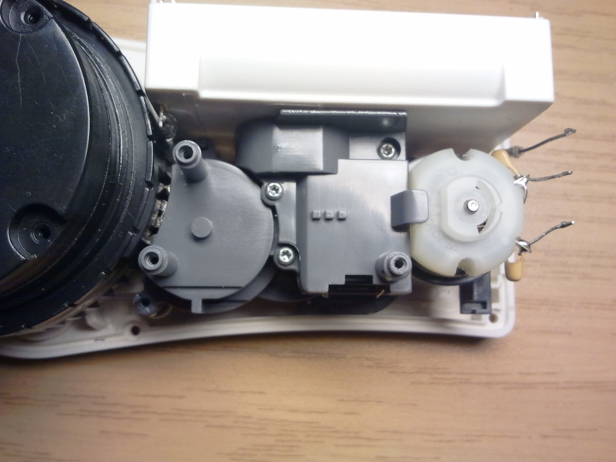
- Motor: direct current motor, moves the key grabber and therefor the key. It was measured to use 3.5V at 0.4A without any load and up to 1A if you try to stop the motor by hand.
- gear box
- snapper: small motor to connect/separate the gear from the key grabber. Uses 3.5V, current unknown.
- key grabber: big black plastic piece connecting the key to the gearbox
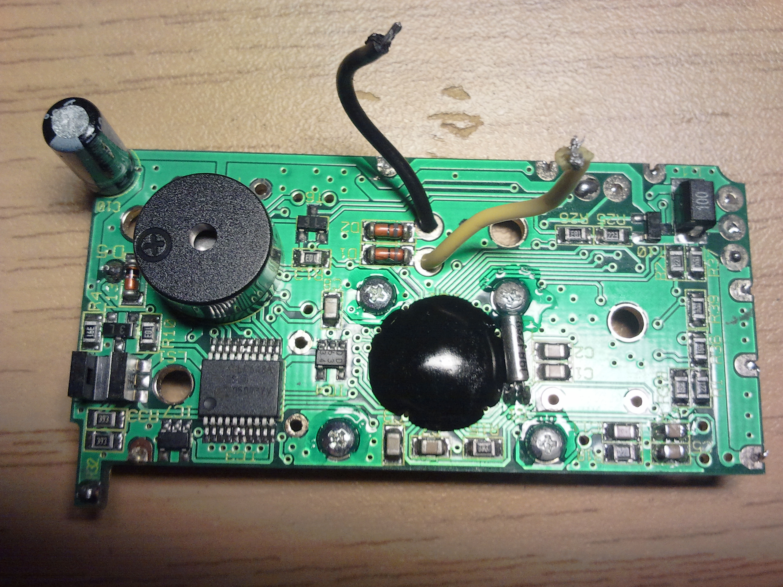
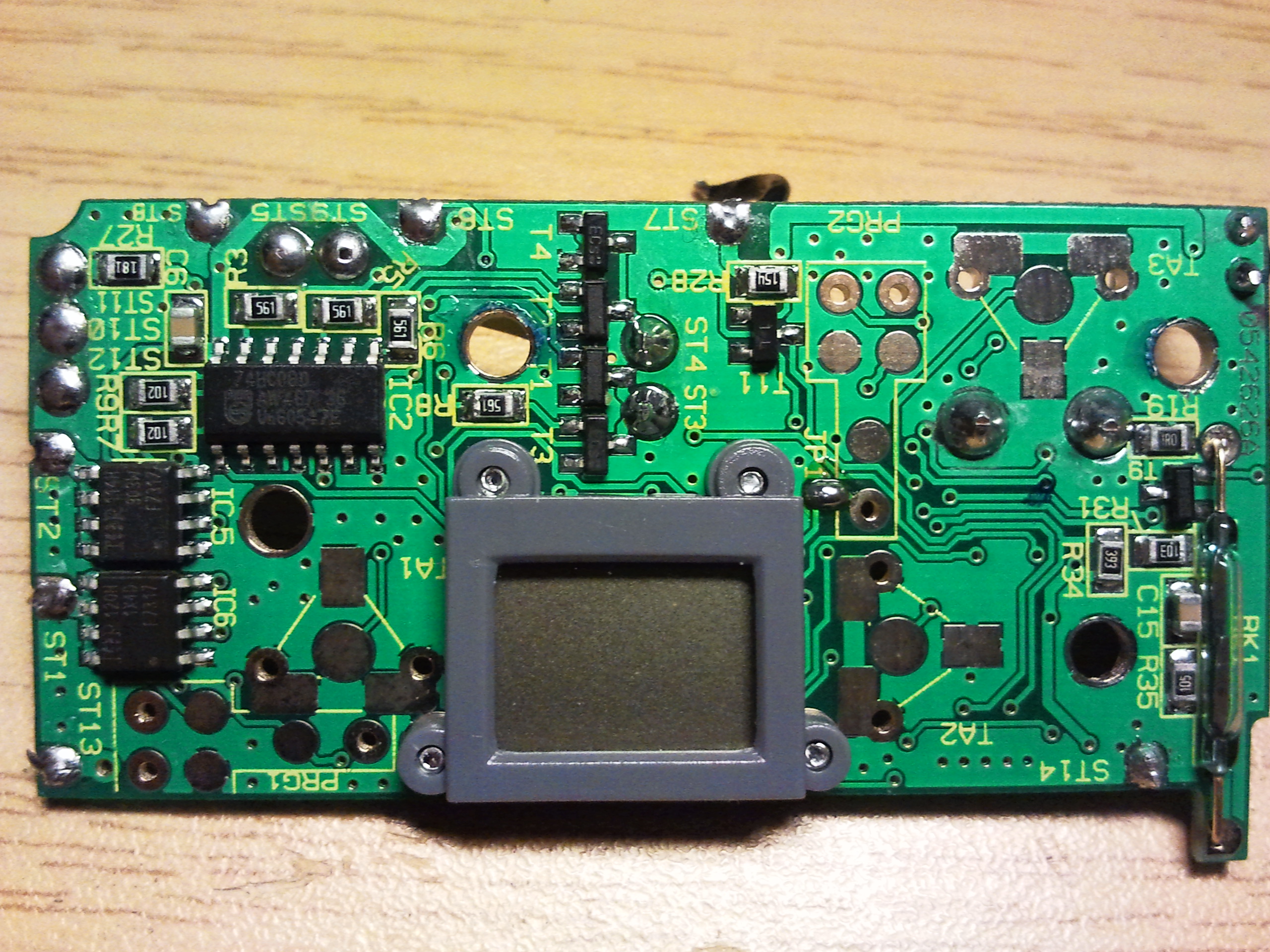
- main board: all functions besides wireless communication is here, it will also keep the key grabber in place. Identified were:
- 1x PIC16LF648A
- 1x Reed contact
- 1x CPI-250
- 1x beeper
- a small display, brand unknown
- 1x 74HC08D
- 1x 120H
- 1x 114H
- some FETs and diods
own Hardware
Developing a small board to replace all three boards. It should power the motors and make them addressable by usb or similar.
- using a socketed usbfoo for logic
- two H-Bridges of type TLE4202 to power the motors
- reuse the CPI-250 as a sensor but get rid of the Reedcontact.

